Automobile chassis body & aerodynamics of vehicle
Automobile chassis body & aerodynamics of vehicle
1.1
Introduction
to chassis frame.
Chassis
is the French term which denotes the whole vehicle. A vehicle Frame also known
as its chassis, is the main supporting structure of a motor vehicle, to which all
other components are attached, comparable to the skeleton of an organism.
1.2
Layout
of chassis frame & its components.
Frame is a under carriage or structure that supports the engine &
cab (body) of the automobile. It is made up of long two members riveted
together with the help of number of cross members.
In automobile there are 3 major types of
construction based on frame.
Ø Conventional frame construction.
Ø Integral frame construction.
Ø Semi-integral frame construction.

Chassis layout Fig- 1.2
1.2. A. Conventional frame construction.
In this type of chassis the
body is made separate unit & then joined with ladder frame. It supports all
the system in a vehicle such as the engine, transmission system, steering
system, suspension system.
Advantages
·
Higher
load carrying capacity & strength.
Disadvantages
·
The
vehicle body tends to vibrate easily & the overall vehicle handling &
refinement is lower.
·
It is
used in truck, bus and in SUV cars bigger vehicles.

Conventional
chassis Frame Fig-1.2.A
1.2. B. Integral frame construction.
In some vehicle half frame
is fixed in the front end on which engine gear box & front suspension is
mounted.
Advantages
·
It has
the advantage when the vehicle is met with an accident the front frame can be
taken easily to replace the damage chassis frame.
·
This
type of frame is used in some of the European & American cars.

Integral Frame chassis construction Fig-1.2.B
1.2. C. Semi-integral frame construction.
This frame is used now days in
most of the cars. There is no frame and all the assembly units are attached to
the body. All the functions of the frame are carried out by the body itself.
Advantages
·
Due to
elimination of long frame it is cheaper & due to less weight most
economical also.
Disadvantages
·
The
disadvantage is repairing.

Semi-integral
chassis frame construction Fig- 1.2.C.
1.2. D. Different types of chassis
construction
A.
Composite
construction.
B.
Unibody
construction.
C.
Tubular
space frame
D.
Glass-fiber body
E.
Carbon-fiber Monocoque
chassis
F.
Aluminium
monocoque
G.
Ladder
chassis frame
A. Composite
construction
·
Composite
construction was the most common type of structure and on the earliest cars of
1900’s.
·
The
chassis & the body are built as the two separate units.
·
The
body is assembled on the chassis with mounting bracket.
·
These
flexible mountings allow the body to move slightly when the car is in motion.
Latest trends of composite construction
·
The
chassis structure contains the powertrain & mechanical components, while
the body is a separate structure.
·
There
are no mechanical links between the body & chassis, which makes it easy to
produce the rolling chassis in large quantities separate from the bodies, and
place different body styles on top of a common structure.

Composite chassis Frame
A. Tubular
space frame
·
Consists
of dozens of circular section tubes (uses square section tubes; for easier
connection to the body panels or circular section provides more strength.
·
High
performance cars require high strength.
·
Tubular
space frame chassis usually incorporate a strong structure under both doors.
·
Eg of
space frame construction is Audi A8, Audi R8, Ferrari 360, Lamborghini
Gallardo, Mercedes –Benz SLS AMG, Pontiac Fiero (GM motors) & Saturn s- series.

Tubular space Frame
Advantages
·
Very
strong in any direction. (Compare with ladder chassis & monocoque chassis
of the same weight).
Disadvantage
·
Very
complex, costly & time consuming to build.
·
Impossible
or mass production.
·
Raised
door sills result in difficult access to the cabin.
B .a. Ultra-light steel auto body
Advantages
·
Stronger
& lighter than conventional
Disadvantages
·
Not
strong & light enough for the best sport cars.
·
Same
structure as that of conventional monocoque.
·
Use of
hydro form parts, sandwiched steel & laser beam welding.

Ultra-light steel auto body
B. b. Aluminium
space frame
·
ASF
consists of extruded aluminium sections; vacuum die cast components &
aluminium sheets of different thickness.
·
At the
highly stressed corners & joints, extruded sections are connected by
complex aluminium die casting.

Advantages
·
Lighter
then steel Monocoque. As space efficient as it.
Disadvantages
·
Still expensive
for mass production.
B .c Lotus
aluminium space frame
·
Chassis
is made of extruded aluminium sections joint by glue & rivets.
·
Aluminium
extruded sections can be made much thinner then tradition welding techniques.
·
Welded
joints are weak, so the thickness of material should be increase throughout a
member just to make a joint strong enough.

Aluminium space frame
Advantages
·
Cheap
or low production. Offers the highest rigidity to weight ratio besides carbon
fibre monoloque.
Disadvantages
·
Not
very space efficient.
A.
Glass-Fiber
body
·
In 1957
lotus pioneered glass –fiber monocoque chassis is elite.
·
Whole
car weighted as light as 660kg.
Advantages
·
Lightweight.
·
Cheap
to be produced in small quantity.
·
Rust
proof.
Disadvantages
·
Lower
visual quality.
·
Unable
to act as stressed member.

Glass-Fiber body
A. Monocoque (Unibody)
·
Monocoque
construction was first widely used in aircraft , starting in the 1920’s
·
Introduction
of monocoque in automobiles in 1922 (Lancia lambda)
·
Monocoque
is one -piece structure which defines the overall shape of the car.
·
Made by
welding several piece together.
·
They
are spot welded together by robot arms (some even use laser welding) in a
stream production line.
·
After
that some accessories like doors, bonnets, boot lid, side panels & roofs
are added.

Monocoque chassis Frame
Advantages
·
Cheap
or mass production.
·
Inherently
good crash protection.
·
Space
efficient.
Disadvantages
·
It’s
very heavy.
·
Impossible
for small volume production.
A. Carbon
fiber monocoque frame
·
A unique and distinct appearance that’s nearly
impossible to replicate.
·
Excellent strength to weight ratio, compared to
other materials.
·
Suitable for complex contours and designs.
·
Superior fatigue properties.
·
High Stiffness.
·
High heat tolerances and resistance.
·
Flexible thermal and electrical properties.
·
Corrosion-resistance (with proper resins).
·
Varying classifications (tensile modulus) of
strength.
·
The strongest carbon fiber is 10x stronger and 5x
lighter than steel.
·
The strongest carbon fiber is 8x stronger and 1.5x
lighter than aluminium.

Carbon fiber monocoque frame
Disadvantages
·
One downside to
carbon fiber body is a lack of flexibility.
·
For instance a
metallic chassis can be heated and straightened or welded if it is slightly
bent or cracked.
·
Carbon fiber
will not bend, once the force of impact is large enough it will crack or
break and repairing it in most cases is not an option.
|
·
Carbon fiber can
be recycled but it loses its strength. Steel and aluminium can be recycled and
become just as strong and useful as it was before.
B.
Ladder chassis frame
It referred to as a
body-on-frame. It gets the ladder in its name from the way it looks. The frame
consists of two long, heavy beams of steel, held together by two shorter pieces.

Ladder chassis frame
Advantages
·
The reason it proved so popular, is its
simplicity.
·
A
ladder frame is easy to design, Build and can be used in multiple
applications with minimal modification.
·
Vehicles with a ladder frame are easier to
assemble, which means a manufacturer can charge less for them
·
heavier good for towing and durability
Disadvantages
·
The construction is heavier, bad for fuel
economy because of the extra weight. .
·
Poor resistance to torsion.
1.4. Various load & Forces acting on chassis
Frame.
Loads on the chassis frame
CHASSIS LOADING
i.
Longitudinal
Torsion
ii.
Vertical Bending
iii.
Lateral Bending
iv.
Horizontal
Lozenging.
i. Longitudinal Torsion
·
Application of
equal and opposite forces act at a certain distance from an axis tends to
rotate the body about the same axis.
·
The frame can be thought as a torsion spring
connecting the two ends where suspension loads act.
·
The resistance to
torsional deformation is called as stiffness and it is expressed in Nm/degree
in SI units.
·
Torsional rigidity is a foremost and primary
determinant of frame performance of cars.

longitudinal Torsion
II. Vertical Bending
·
Weight of driver,
engine, drive-train, radiator and shell etc. under an effect of Gravity produces
sag in the frame as shown in Figure 2.
·
Frame is assumed
to act as simply supported beam and four wheels as supports tend to produce
reactions vertically upward at the axles.
·
Vertical dynamic
forces due to acceleration/deceleration further increase the vertical
deflections, hence stresses in chassis.

Vertical Bending
III. Lateral Bending
·
Lateral bending
deformation occurs mainly due to the centrifugal forces caused during Cornering
and wind forces to some extent.
·
Lateral forces act
along the length of chassis and is resisted by axles, tires and frame members viz.
hoops, side impact members and diagonal hoops etc.

Lateral Bending
IV. Horizontal Lozenging.
·
This deformation
is caused by forward and backward forces applied at opposite wheels
·
These forces may
be caused by vertical variations in the pavement or the reaction from the road
driving the car forward.
·
These forces tend
to distort the frame into a parallelogram shape as shown in the Figure.
·
The magnitude of these loads changes with the
operating mode of the car.
·
It is generally
thought that if torsional and vertical bending stiffness is satisfactory, then
the chassis structure is expected to perform well. But torsional stiffness is
given more weight-age as the total cornering traction is the function of
lateral weight transfer.


Load acting on the frame
·
Material properties
of the Truck Chassis (high strength structure steel)
Material Properties
·
Young Modulus 200GPa
·
Poisson Ratio 0.33
·
Density
7827.08kg/m3
Symmetry Linear isotropic 76
In the finite element analysis
of the truck chassis, the linear
Isotropic material model of
high strength structural steel was used.
OVER ALL DIMENSIONS OF THE CHASSIS
All over length :
7956 mm
All over width : 4400
mm
All over height : 4500 mm
Wheel base: 4100 mm
Wheel tread: 3450 mm
·
Weight of the
Vehicle
·
Total Weight of
the Vehicle and Payload.
Pay load
|
534645N
|
NVW
|
426735 N
|
Maximum GVW
|
961380 N
|
Convert =kg X 9.81=N
3.3.1 Calculation of Bending
and Torsion Case Load
Consider a simply supported
beam.

FFT =
F1V + F2V
FRT =
F3V + F4V
Where, WB =
Wheel Base
FFT =
Force at Front Tire
FRT
= Force at Rear Tire
According to the equation of
equilibrium condition
∑H = 0, ∑V = 0, ∑M = 0

Force
at front tire (FFT).
2/3
WB =0.66x4100= 2706 mm
1/3
WB = 0.33 x 4100=1366 mm
Taking
moment at front (F) i.e. MF = 0
FRT × 4100 = 961380
x2706
FRT =
961380x2706/4100= 634510N
Force at front tire (FRT).
Taking
moment at front (F) i.e. MR = 0
FFT × 4100 = 961380
x1366
FFT = 961380 x
1366/4100= 320303N
·
Bending
load acting on the frame.
Assume around 24 bolts used on Front side
& 4 used on rear side
·
Front
suspension load at each bolt: FFT = 320303/24=13345N.
·
Rear
suspension load at each bolt: FRT = 634510/4=158627N
Torsion Load acting on the frame
Load distribution of the tire for torsion load conditions

Torsion Load acting on the frame
Right ramp loading.
F1v
= 0 N
FFT
= F1v + F2v
FFT = F2v = 320303N
F4v × RT = (GVW x
RT/2) + {RT+ (FT-RT)/2 F2v}
Taking moment at a
rear right tire point i.e. (M F4v = 0)
Left
Ramp Loading
F2v
= 0 N
F3v
× RT = (GVW x RT/2) - (F2v) x (FT-RT)/2 +RT
F
RT = F3V + F4V
GVW
= 961380 N
RT
=2920 mm
FT = 3480 mm
F2v =
320303 N
F4v × RT = (GVW x
RT/2) + {RT+ (FT-RT)/2 F2v}
F4v × 2920 =
(961380 x 2920/2) + {2920+ (3480-2920)/2 x 320303}
F4V ×2920 =1403614800+89687760
F4V = 511404.9N.
160250
= F3V + 511404
F3V = 160250 –
511404
F3V= -351154N.
1.5 Explain different types of drive train.
1.5. A. Front-wheel-drive layouts
Front-wheel-drive
layouts are those in which the front wheels of the vehicle are driven. The most
popular layout used in cars today is the front-engine, front-wheel drive – with
the engine transversely in front of the front axle, driving the front wheels.
·
Advantages of FWD

Front-wheel-drive layouts
·
Interior space:- Since the powertrain is a
single unit contained in the engine compartment of the vehicle, there is no
need to devote interior space for a driveshaft tunnel
or rear differential, increasing the volume available for passengers and
cargo.
·
Weight: - Fewer components usually mean lower
weight. Improved fuel efficiency due
to less weight.
·
Cost: -
Fewer material components and
less installation complexity overall.
·
Improved drivetrain efficiency:- the direct connection between engine and transaxle
reduce the mass and mechanical inertia of the
drivetrain compared to a rear-wheel-drive vehicle
·
Assembly efficiency: - the powertrain can
often be assembled and installed as a unit, which allows more efficient
production.
·
Traction: - Placing the mass of the
drivetrain over the driven wheels moves the centre of gravity farther
forward than a comparable rear-wheel-drive layout, improving traction and
directional stability on wet, snowy, or icy surfaces.
Disadvantages of FWD
·
Front-engine front-wheel-drive layouts are
"nose heavy" with more weight distribution forward, which makes them
prone to under steer,
especially in high horsepower applications.
·
Torque steer is the
tendency for some front-wheel-drive cars to pull to the left or right under
hard acceleration
·
In a vehicle, the weight shifts back during
acceleration, giving more traction to the rear wheels. This is one of the main
reasons nearly all racing cars are rear-wheel drive.
·
Turning circle – FWD layouts almost
always use a transverse engine ("east-west")
installation, which limits the amount by which the front wheels can turn, thus
increasing the turning circle of a front-wheel-drive car compared to a
rear-wheel-drive one with the same wheelbase.
·
The FWD transverse engine layout
(also known as "east-west") restricts the size of the engine that can
be placed in modern engine compartments, so it is rarely adopted by powerful
luxury and sports cars.
·
It makes heavier use of the front tyres
(i.e., accelerating, braking, and turning), causing more wear in the front than
in a rear-wheel-drive layout.
1.5. B. Rear -wheel-drive layouts
Rear-wheel
drive (RWD) typically places the engine in the front of the vehicle and the
driven wheels are located at the rear, a configuration known as front-engine, rear-wheel-drive layout (FR
layout).

Rear -wheel-drive layout
Advantages of RWD
·
Weight transfer during
acceleration – During heavy acceleration, weight is placed on the rear, or
driving wheels, which improves traction.
·
Better braking – the more even weight
distribution helps prevent lockup from the rear wheels becoming unloaded under
heavy braking.
·
Can accommodate more powerful engines as a
result of the longitudinal
orientation of the drivetrain, such as the inline-6, 90°
big-bore V8, V10 and V12 making
the FR a common configuration for luxury and sports cars.
·
Road grip feedback – front wheels are
not affected by engine and gearbox, thus allowing for better feeling of tyre
grip on road surface.
Disadvantages of RWD
·
Under heavy acceleration (as in racing), over
steer and fishtailing may
occur as the rear wheels break free and spin.
·
On snow, ice and sand, rear-wheel drive loses
its traction advantage to front- or all-wheel-drive vehicles, which have
greater weight on the driven wheels.
·
Decreased interior space – Though
individual designs vary greatly, rear-wheel-drive vehicles may have: Less front
leg room as the transmission tunnel takes up a space between the driver and
front passenger, less leg room for centre rear passengers.
·
Increased weight – The components of a
rear-wheel
-drive vehicle's power train are less complex, but they are larger.
The driveshaft adds weight.
·
Higher initial purchase price – Modern
rear-wheel-drive vehicles are typically more expensive to purchase than
comparable front-wheel-drive vehicles.
1.5. C. Four wheel drive layout
Four-wheel drive,
also called 4×4 ("four
by four") or 4WD
refers to a two-axle vehicle drivetrain capable
of providing torque to all
of its wheels simultaneously. It may be full-time or on-demand, and is
typically linked via a transfer case providing
an additional output drive-shaft and, in many instances, additional gear ranges.

Four wheel drive layout
Advantages of 4WD
·
Traction is nearly doubled compared to a
two-wheel-drive layout. Given sufficient power, these results in unparalleled
acceleration and driveability on surfaces with less than ideal grip, and
superior engine braking on loose surfaces.
·
A well-balanced 4WD configuration will not
degenerate into either under steer or over steer, but instead break traction of
all 4 wheels at the same time into a four-wheel drift.
Disadvantages of FWD
- 4WD systems require more machinery and complex transmission components, and so increase the manufacturing cost of the vehicle and complexity of maintenance procedures and repairs compared to 2WD designs
- 4WD systems increase powertrain mass, rotational inertia and power transmission losses, resulting in a reduction in performance in ideal dry conditions and increased fuel consumption compared to 2WD designs
- The handbrake may not be used to induce over steer for manoeuvring purposes, as the drivetrain couples the front and rear axles together. To overcome this limitation, some custom prepared stage rally cars have a special mechanism added to the transmission to disconnect the rear drive if the handbrake is applied when the vehicle is moving.
1.5. D. Individual Wheel Drive (IWD)
IWD is the drivetrain used in
most electric cars, which are gaining more popularity as we are heading towards
an electric car-driven world the figure below shows individual wheel
drive system. As each wheel is powered by a separate motor, greater traction.

Individual
Wheel Drive (IWD
Advantages
of individual wheel drive (IWD)
·
Control is achieved, compared to Front wheel
drive or Rear wheel drive, in which, the non-powered wheels also.
·
Contribute to the resistance but doesn’t contribute
much to traction. The gears are only used to increase the torque.
·
An Electric vehicle with individual wheel
drive has greater control. These vehicles don’t need long and heavy duty
·
It provides
sportier handling and traction for a wide range of car
Disadvantages
of individual wheel drive (IWD)
·
It increases fuel consumption.
·
It increases the complexity and weight of cars.
·
It is not suitable for extreme off-road condition.
1.6.
Different types of cars.
a.
Convertible
·
A convertible is a car which features a
retractable roof – in other words, a roof that can be folded down or removed
either partially or in its entirety.
·
Convertible cars have a roof which may either
be folded via an electronic or manual mechanism, or alternatively the top roof
panel may be removable and stored in a compartment somewhere when the driver
wants to experience open-top driving.
·
E.g. Mazda MX-5, Porsche 718 Boxster, Audi A3, Mercedes E-Class, Porsche 911
, Audi A5 Cabriolet, Jaguar F-Type, BMW 4
Series Convertible.

Convertible
bb. SUV cars
•
An SUV is a
passenger vehicle, which combines the towing capacity of a pickup truck with
the passenger-carrying space of a sedan.
•
They have a
powerful engine, have sufficient passenger space along with luggage compartment
behind the rear row seats and are designed for all terrains.
•
They are
non-commercial vehicles with the BIW built on the chassis similar to a light
truck or a crew cab
•
An off roader
needs a long hood and an upright position. That lends the Vehicle
self-assuredness and power.
•
E.g.- Maruti Suzuki Vitara, Mahindra KUV100 Facelift, Mitsubishi Pajero Sport
Facelift, BMW X2, Nissan Qashqai, Isuzu MU-X Facelift 2018.


·
Coupes are stylish cars best for singles or
couple
·
The doors tend to be wider and the roof
lower. It is shorter than a sedan and may or may not have a back seat. If there
is back seating, it might be a little tighter than you may find comfortable.
·
E.g. - Mercedes-Benz, Mercedes-AMG C-Class: Recall
Alert, Mercedes-AMG S63, Maserati GranTurismo, Lexus, Subaru.


coupe car
d. Hatchback cars
·
A hatchback is smaller than an SUV or minivan, but
larger than a sedan. The main difference between a hatchback and a sedan is the
extended trunk. Instead of the back sloping downwards, the back area is lifted,
providing extra space for cargo.
·
Typically, the hatchback has a top-hinged trunk
with rear seats that fold down for even more cargo space. As a result,
hatchbacks are usually marketed as small family cars or executive cars.
·
Since the interior space can be made to prioritize
passengers or cargo, they are a popular and practical choice for those who need
both. From small city hatchbacks to large luxury models, there is a wide
variety of hatchbacks available to you.
·
E.g. Maruti Swift, Maruti Baleno, Maruti Alto, Hyundai Elite i20,
Renault KWID. Maruti Wagon R.

Hatchback cars
e. Sedan cars
·
A sedan, also known as a saloon in other
countries, is the most popular body style. It typically features two rows of
seats, 4 doors, and a 3-box configuration.
·
Sedans tend to provide better fuel economy,
affordability, handling, and performance.
·
Since they are closer to the ground and have
a lower centre of gravity, they tend to perform better around corners and sharp
turns than larger vehicles such as SUVs. As a result, they are much less prone
to tipping and rolling over than trucks and SUVs.
·
E.g. Fiat Viaggio, Tata
Tiago EV, Renault Talisman, Volvo C70, Hyundai
Sonata Facelift, Honda Civic.

Sedan cars
f. Crossover cars
·
A cross between a sedan and an SUV,
crossovers (also known as Crossover Utility Vehicles) give you the best of both
worlds.
·
They are available in four-wheel, rear-wheel,
and all-wheel drives.
·
They are cheaper and have better fuel economy
than full-sized SUVs while still giving you extra ground clearance and a more
commanding view of the road.
·
E.g. Mahindra U321 MPV, Mahindra TUV300
Plus, Nissan Kicks, Renault Duster facelift, Tata Q501 (codename), MG GS
Concept, Datsun Go-Cross.

Crossover cars
g. Electric cars
The
heart of an electric car is the combination of:
·
The motor's controller
·
The batteries
The
controller takes power from the batteries and delivers it to the motor. The accelerator pedal hooks to a pair of potentiometers (variable resistors), and these potentiometers
provide the signal that tells the controller how much power it is supposed to
deliver. The controller can deliver zero power (when the car is stopped), full
power (when the driver floors the accelerator pedal), or any power level in
between.


E.g. - Tata Tiago, Tata Tigor, Renault Zoe, Mercedes-Benz EQ Concept, Hyundai
Ioniq
Advantage of Electric Vehicle
·
Zero emission
·
Power Regeneration
·
Low noise pollution
·
Instant start and direct drive.
Disadvantage of Electric Vehicle
·
Limited
Range
·
Long
Refuelling Time
·
Higher
Cost
·
Lack of
Consumer Choice
h. Fuel Cell
Electric Vehicle (FCEV)
·
FCEVs also go by the name Fuel Cell Vehicle
(FCV).
·
They got the name because the heart of such
vehicles is fuel cells that use chemical reactions to produce electricity.
·
Hydrogen is the fuel of choice for FCVs to
carry out this reaction, so they are often called ‘hydrogen fuel cell
vehicles’.
·
FCVs
carry the hydrogen in special high pressure tanks, another ingredient for the
power generating process is oxygen, which it acquires from the air sucked in
from the environment.
·
Electricity generated from the fuel cells goes
to an electric motor which drives the wheels. Excess energy is stored in
storage systems like batteries or super capacitor


·
E.g. Hyundai Tucson Fuel
Cell, Toyota Mira, Honda Clarity Fuel Cell.
Working
·
The Fuel gas (hydrogen rich) is passed towards the
anode where the following oxidation reaction occurs:
H2 (g) = 2H+ + 2e-
·
The liberated electrons from hydrogen in anode side
do not migrate through electrolyte.
·
Therefore, they pass through the external circuit
where work is performed, then finally goes into the cathode.
·
On the other hand, the positive hydrogen ions (H+)
migrate across the electrolyte towards the cathode
·
At the cathode side the hydrogen atom reacts with
oxygen gas (from air) and electrons to form water as byproduct according to:
·
The liberated electrons from
the hydrogen are responsible for the production of electricity.
·
The
water is produced by the combination of hydrogen, oxygen and liberated
electrons and is sent out from the cell.
·
The
DC current produced by fuel cell is later converted into AC current using an
inverter for practical application.
·
The
voltage developed in a single fuel cell various from 0.7 to 1.4 volt.
·
More
power can be obtained by arranging the individual fuel cell as a stack. In this
case, each single cell is sandwiched with one another by a interconnect.
Advantages
·
Zero Emissions: a fuel cell vehicle only
emits water vapors. Therefore, no air pollution occurs.
·
High efficiency: Fuel cells convert chemical
energy directly into electricity without
the combustion process. As a result, Fuel cells can achieve high efficiencies
in energy conversion.
·
High power density: A high power density allows
fuel cells to be relatively compact source of electric power, beneficial in
application with space constraints.
·
Quiet operation: Fuel cells can be used in
residential or built-up areas where the noise pollution can be avoided.
·
No recharge: Fuel cell systems do not
require recharging.
Disadvantages
·
It is difficult to manufacture and stores a high
pure hydrogen
·
It is very expense as compared to battery
I . Hybrid cars
A hybrid vehicle uses
two or more distinct types of power, such as internal combustion engine to
drive an electric
generator that powers an electric, e.g. in diesel-electric
trains using diesel engines to drive an electric generator that
powers an electric motor, and submarines that use diesels when surfaced and
batteries when submerged. Other means to store energy include pressurized fluid
in hydraulic hybrids.
E.g. - Toyota Camry Hybrid,
Toyota Avalon Hybrid, Chevrolet Bolt, Ford
Fusion Hybrid, Toyota Prius, Kia Optima Hybrid, Hyundai Ioniq, Honda
Accord Hybrid. Find Best Price.
I.
Series hybrid cars
The series hybrid has the generator driven by the engine. This generator
is used to charge the batteries and also drive the electric motor, which drives
the transmission. Thus power to the vehicle is never directly given by the
engine.

II.
Parallel hybrid cars
In a parallel hybrid vehicle an electric motor and an
internal combustion engine are coupled such that they can power the vehicle
either individually or together. Most commonly the internal combustion engine,
the electric motor and gear box are coupled by automatically controlled
clutches. For electric driving the clutch between the internal combustion
engine is open while the clutch to the gear box is engaged. While in combustion
mode the engine and motor run at the same speed.

Advantages of Hybrid Cars
·
Very less pollution.
·
Better mileage.
·
More reliable and comfortable.
·
Very clean cars due to less emission.
·
Batteries need not be charged by an external
source.
·
Warranties ava
·
Less dependence on fuels.
Disadvantages
of Hybrid Cars
·
The initial cost will be very high – higher than
other cars.
·
Since a lot of batteries will be needed, the car
will be very heavy.
·
As there are electrical components, there is risk
of shock during an accident.
·
The vehicle can be repaired only by professionals.
·
Spare parts will be very costly and rare.

Power transmission
1.7 Aerodynamics of a car body
A branch of
dynamics that deals with the motion of air and other gaseous fluids and with
the forces acting on bodies in motion relative to such fluids.
1.7. a. Advantages of aerodynamics
It is essential that
aerodynamics be taken into account during the design of cars as an improved
aerodynamics in car would attain.
·
More
fuel efficiency
·
Higher
speeds
·
Good
aesthetics & stylish appearance of car
·
More
stability of car at higher speed
·
Reduces
noise level
1.7. b. Methods of
Aerodynamic Testing
The two main
alternative test methods, which are the most commonly used in aerodynamic
development and testing of cars, are Computational Fluid Dynamics (CFD) and
wind tunnel testing.
·
Wind
tunnel Testing
Wind tunnel testing has the big
advantage that once the vehicle model is produced and rigged in the wind tunnel
test section, it can quickly provide highly accurate data. Data for different
boundary conditions, such as different wind speeds and yaw angles, can be
acquired quickly. If similar changes in conditions are done on a computer
model, the whole simulation has to be run over again for each case. On the other
hand, wind tunnel testing can
be both highly costly
and time consuming.
Open & close circuit wind tunnel testing
Open & close circuit wind tunnel testing


·
Computational Fluid
Dynamics
Computational fluid dynamics (CFD) is one of the branches of fluid
mechanics that uses numerical methods and algorithms to solve and analyse
problems that involve fluid flows. Computers are used to simulate the interaction
of liquids and gases with surfaces defined by boundary conditions. Even with high-speed supercomputers only approximate
solutions can be achieved in many cases.
1.7. c. Aerodynamics forces acting on body
In order to improve the aerodynamics
of cars, we must know how the flow of air past a car. The major forces which
affecting the motion of car in fluid flow are.
·
Drag
force
·
Lift or
down force
·
Side
force
·
Drag force
Some energy is lost to move the car
through the air & this energy is used to overcome a drag force. In vehicle
aerodynamics drag is due to frontal pressure & Rear vacuum.
For calculating drag force following formula
is use
F= ½ CDAV2
Where F=
Aerodynamics drag force A= frontal area
C=coefficient of drag V=velocity of object
D= density off air
·
The drag coefficient is a function of the shape
of the object and the Reynolds Number (Re)
·
Re = (velocity * length-scale) / (kinematic
viscosity)
·
There are several good ways to calculate the
frontal area of your vehicle. One is to simply measure the height multiplied by
the width and take 85% of it to acuminate the smaller green house.
F.A. = (height x width) x 0.85
F.A. = (height x width) x 0.85
Calculating drag force for Toyota Prius C
Dimensions
Wheel base - 2550mm
Length – 4000mm
Width – 1690mm
Height – 1450mm
F drag =1/2 x δxV2 x D x A
T air = 670F
T0C = (T0F
– 32) x (5/9) = (67-32) x (5/9) = 19.40C
Ꝭ = density of air =1.204 kg/m3
at 19.40C temp
D= drag coefficient for Toyota Prius C = 0.28
A= Frontal area of Car = W x H x 0.85 = 1690 x 1450 x 0.85= 2.0336m2
V= 6km/hr. x 1hr/3600sec x 1000/1km = 1.6Km/hr.
F drag =1/2 x 1.204 x (1.6)2 x 0.28 x 2.0336 = 0.87461W
Y=0.2275 X2 +0.3187X
(as per equation y=ax2+bx)
As the car is moving 30km/hr from 0 to 9.25sec
F drag =0.2275 t2 +0.3187t
9.25 9.25
9.25
ʃ F drag dt = ʃ
(0.2275t2 + 0.3187
t ) dt = [ 0.2275t3/3 + 0.3187t2/2]
0 0
0
=73.653N.S
9.25
F drag
= ʃ F drag dt /Δt = 73.653/9.25 = 8N
0
·
Lift force
It is the force produced by the
pressure difference between above & below of the vehicle.
(FL) = CL q A = (CL (1/2) r V2)
A
Where
CL =
Coefficient of Lift
q = Dynamic Pressure in the Test Section
r = Mass Density of Air
A = Frontal Area of Vehicle
V = Velocity
q = Dynamic Pressure in the Test Section
r = Mass Density of Air
A = Frontal Area of Vehicle
V = Velocity
·
Side force
It is produced by the action of
side winds.
(FS) = CS q A = (CS (1/2) r
V2) A
Where
CS =
Coefficient of Side Force
q = Dynamic Pressure in the Test Section
r = Mass Density of Air
A = Frontal Area of Vehicle
V = Velocity
r = Mass Density of Air
A = Frontal Area of Vehicle
V = Velocity
1.7. f. METHODS TO REDUCE DRAG
·
Vortex Generators
·
Diffuser
·
Rear Fairing
·
Streamlining
·
Spoilers
·
Vortex
Generators
A vortex
generator (VG) is an aerodynamic device, consisting of a small vane usually
attached to a lifting surface (or airfoil, such as an aircraft
wing) or a rotor blade
of a wind turbine. VGs may also
be attached to some part of an aerodynamic vehicle such as an aircraft fuselage
or a car. When the airfoil or the body is in motion relative to the air, the VG
creates a vortex, which, by removing
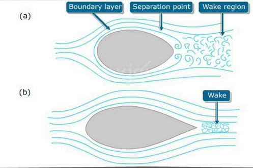
some part of the slow-moving boundary layer
in contact with the airfoil surface, delays local flow separation and aerodynamic
stalling, thereby improving the effectiveness of wings and control surfaces,
such as flaps, elevators, ailerons, and rudders. If the air that makes up the vortex can be tripped before it leaves
back of the car, it will make smaller vortices, which will have a smaller
effect on the overall aerodynamics of the vehicle.


Bump shape vertex generator
·
Concept of a Vortex
The laminar boundary layer flow is a
very smooth flow, with no disruption between the layers. It has low skin
friction drag but it is unstable, which means that flow separation is easier
when it has laminar behavior at high angles of attack. Laminar flow airfoils tend to provide low
drag at cruise but nasty stall characteristics. Turbulent boundary layer is
characterized by chaotic property changes. The flow has more energy and has
rapid variations of pressure and flow velocity in space and time - turbulence is complex and therefore
turbulent flow is more complex to simulate. In turbulent flow, drag caused by
boundary layer skin friction increases. shows a good intuitive approach of the
transition process.

Vertex
flow of Air
·
Diffusers
It works by providing a space for the
under body airflow to decelerate and expand (in area, as density is assumed to
be constant at the speeds that cars travel) so that it does not cause excessive flow
separation and drag, by providing a degree of "wake infill" or more accurately, pressure recovery. The diffuser itself accelerates the
flow in front of it, which helps generate down
force.


Diffusers
· Operation
The
pressure under the car is affected by the diffuser so that it can expand back
to ambient in the diffuser, as the car moves through the air. It uses Bernoulli's principle, such that the pressure decreases while
the velocity increases. Since the pressure below the car is lower than on the
side and above the car, down force is produced if implemented correctly. The
diffuser "drives" the under body, which produces the down force.
·
Rear
Fairing
A structure on various parts of
a vehicle, for example an aircraft, automobile, or motorcycle, that produces a smooth exterior and
reduces drag.

Rear fairing in jet
·
Streamlining
A streamlined body is a shape
that lowers the friction
drag between a fluid, like air and water, and an object moving through that
fluid. Drag is a force that
slows down motion; friction drag is a special kind of drag. It occurs when the
fluid closest to the object sticks to its surface, exerting a force that
opposes the object’s motion.
Particles of a
continuous fluid can be considered to travel along smooth continuous paths
which are given the name streamlines.
These streamlines can be curved or straight, depending on the flow of
the fluid. This type of motion is also called laminar flow. Streamline motion
is not the only possible kind of fluid motion.
When the motion becomes too violent, eddies and vortices occur. The motion becomes turbulent.
Streamlining
·
Effect of wake on streamlining
The rear-end shape of a car is one of the most important parts
from the view point of aerodynamics. It governs the aerodynamic characteristics
of the car, especially drag and rear lift. However, a rear-end shape like a
spoiler often increases drag on recent low-drag cars. The relation of rear-end
shape to drag and lift is studied by consideration of the wake structure, which
is obtained by wind tunnel testing and CFD. Finally, a new rear shape which
reduces rear lift without increasing drag and front lift is discussed

Effect of wake
·
Spoilers
A spoiler is an automotive
aerodynamic device whose intended design function is to “spoil” unfavorable air
movement across a body of a vehicle in motion, usually described as drag.
Spoilers on the front of a vehicle are often called air dams, because in
addition to directing airflow they also reduce the amount of air flowing
underneath the vehicle, which generally reduces aerodynamic lift and drag.
Spoilers are often fitted to race and high-performance sports cars, although
they have become common on passenger vehicles as well. Some spoilers are added
to cars primarily for styling purposes and have either little aerodynamic
benefit or even make the aerodynamics worse.The goal of many spoilers used in
passenger vehicles is to reduce drag and increase fuel efficiency. Passenger
vehicles can be equipped with front and rear spoilers. Front spoilers, found
beneath the bumper, are mainly used to decrease the amount of air going
underneath the vehicle to reduce the drag coefficient and lift. Sports cars are most commonly seen with front
and rear spoilers.


Spoilers
·
CFD(Computational fluid dynamics)
“CFD
(Computational fluid dynamics) is a set of numerical methods applied to obtain
approximate solution of problems of fluid dynamics and heat transfer.”
The
physical characteristics of the fluid motion can usually be described through
fundamental mathematical equations, usually in partial differential form, which
govern a process of interest and are often called governing equations in CFD. The computational part simply means the study
of the fluid flow through numerical simulations, which involves employing
computer programs or software packages performed on highspeed digital computers
to attain the numerical solutions.


CFD
codes are structured around the numerical algorithms that can handle fluid flow
problems. All the CFD commercial packages available in the market have three
basic elements, which divide the complete analysis of the numerical experiment
to be performed on the specific domain or geometry. The three basic elements
are
I .
Pre-processor
ii. Solver
iii. Post-Process


Very nice blog. Easy to understand.
ReplyDeleteWell done...
ReplyDeleteSir, tuition lete ho kya